 |
|
Solar Seeker Project Guideline
 |
The solar seeker device allows one to create a prototype of an adaptive solar energy system where the solar panel can be optimized to produce the most energy. The basic idea is to mount two solar panels on a rotating structure. A robotic control technique can be used to make sure the two solar panels are oriented to face directly to the sun (or the brightest light source).
This prototyping structure has three components:
|
1. Solar Panel Frame Assembly
Required Parts
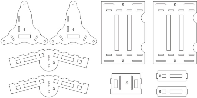
- There are five pieces for the frame, each a labeled with numbers from 1-5. Get two of each except for part number 4.
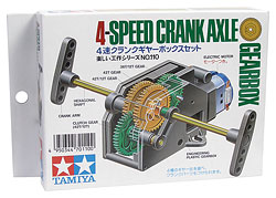
- One Tamiya 4-speed crank axle gearbox. Gearbox assembly procedures are inside the box. Assemble using the highest gearing ratio (5402:1).
- Two sets of screw/nuts.
- Four sets of #4 screw/nut. They are labeled "P". These screws will be used to mount the top panel of the frame (part number 2) to the motor's axle.
- Two screws. They are labeled "M". These screws will hold the motor body to the panel (part number 4)
Assembly Procedure:
[Click image for a larger version]
 |
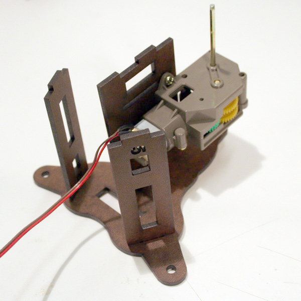 |
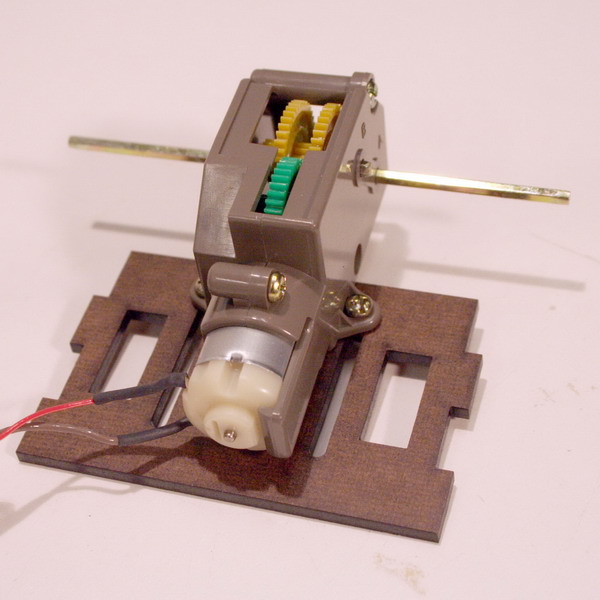
| 1. Assemble the Tamiya motor at the highest gearing ratio (5402:1). Solder the motor control wires. Screw the motor to part number 4 using the screws labeled "M". | 2. Lay part number 1 on a table. Attach part number 4 and make sure the motor axial goes through the top hole of part number 1. Attach two pieces of part number 5 to the base of part number 1. |
 |
 |
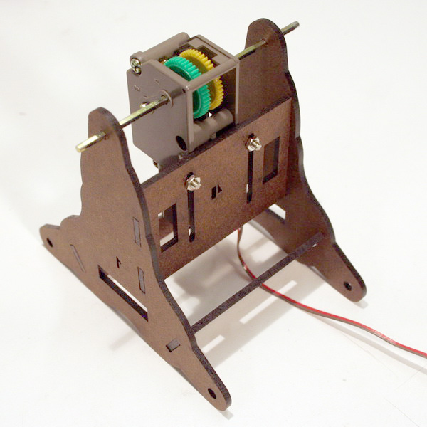
3. Attach the second piece of part number 1. |
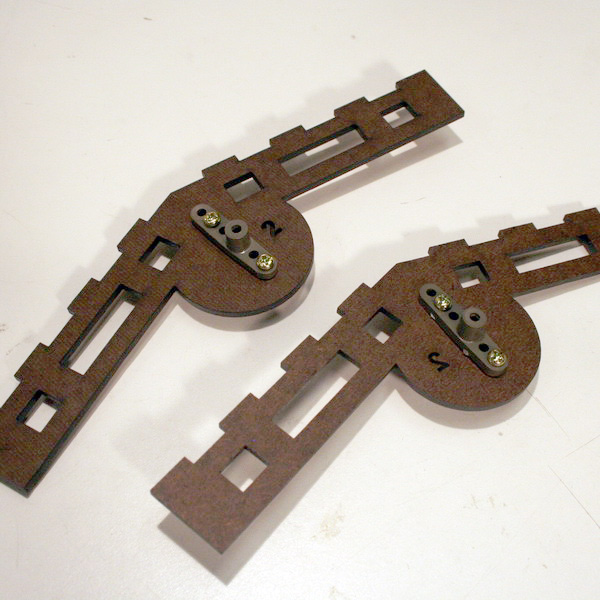
4. Screw the Tamiya motor cranks to part number 2 using the screws and nuts labeled "P". |
 |
 |
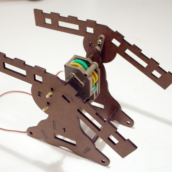
5. Attach the crank from step 4 to the motor axial. The stand is now complete. |
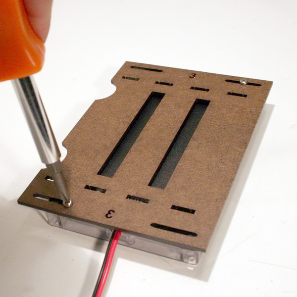
6. Place the solar panel on part number 3. Screw it in place. |
 |
 |
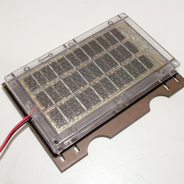
7. The top side should appear as shown in the above image. |
8. Turn the stand from step 5 upside down and attach it to the solar panel from step 7. Do the same for both solar panels. |
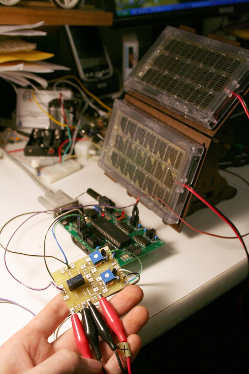
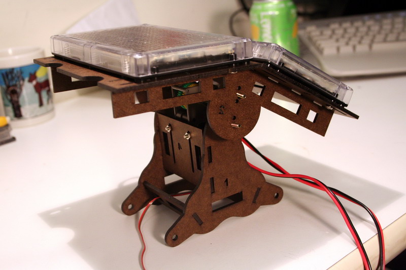
Photo sample of the completed solar seeker |
|
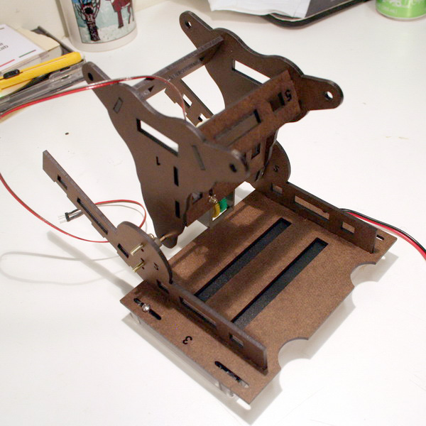
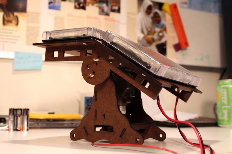
Another photo of the completed solar seeker |
|
2. The Sensing Circuit
Required Components
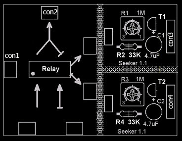
Description Sensor Circuit PCB Latching Relay 1 MOhm Potentiometer 33 KOhm Resistor 4.7 uF Polarized Capacitor 2N3904 Transistor Male header / wires set Power jack / wire set Assembly Procedure:
[Click image for a larger version]
1. Solder all the components to the circuit board. |
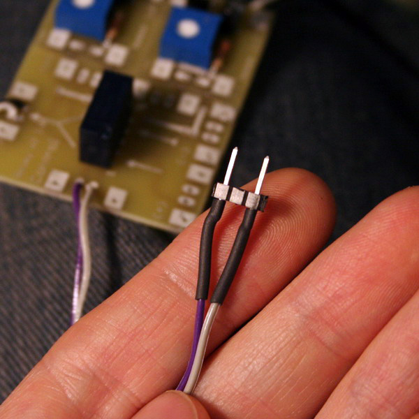
2. Solder two wires to CON1. The other end connects to a male connector. Use a 3x1 connector with the middle pin removed. Polarity is NOT important. |
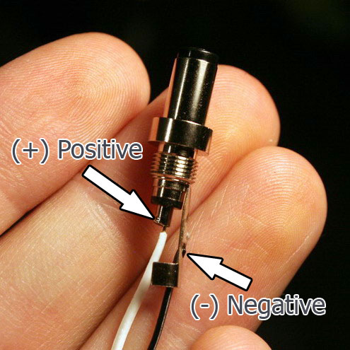
3. Solder two wires to CON2. Connect the other end to the power jack. Make sure the positive is on the inside. |
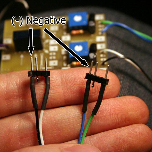
4. Solder two wires to the outer two pins of CON3. Solder the other end to a 4x1 male connector with the third pin removed. Do the same for CON4. Note that the middle unused pin helps to correctly orient the connector when plugging into the gogoboard. |
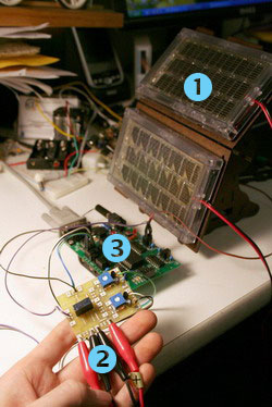
3. Integration with the Gogoboard
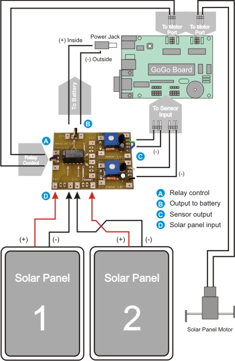
Operation
The solar panel has two functions. One is to change batteries and the other is to sense the direction of light (from the sun in most cases). But the solar panels can perform only one function at a time. Thus, a relay is used to switch between the two modes. This relay is controlled by the gogoboard. Here's what happens in each mode:
Charging Mode:
Power from the solar panels goes through the relay directly to the the power jack, which connects to batteries. No power is fed through the sensors. Thus, no sensor reading is available in this mode.
Sense Mode:
The relay directs the power from the solar panels to the sensor ports allowing the gogoboard to decide how to control the panel's direction. No battery charging takes place in this mode.
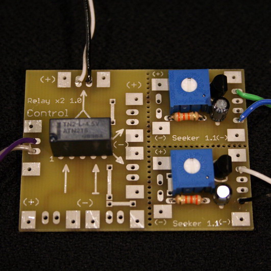
While in sensing mode, the potentiometer (the blue parts on the circuit board) allows calibration of the sensor readings. The sensitivity of the sensor can be adjusted by turning the dial.
Photo sample of the assembled solar seeker